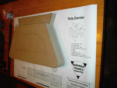
The first part I tackled on the B9 project was the treadsection. I purchased the Waist-to-Treadsection
plans from Bermuda Triangle Engineering and they are
well worth the price. Here is the build along with tips I've learned, some of them the hard way.
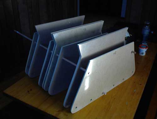
Here are the eight sides of the treadsection cut out of 1/4" and 1/2" medium density
fiberboard (MDF) and temporarily screwed together for
sanding. First mistake--I put the short sides and long sides together for ease of sanding rather
than putting them in the proper order. Since I can't sand straight when I reordered the side they
didn't match up and I had to resand making the entire treadsection slightly smaller than called for.
The plans I've purchased call for using plywood for the treads and covering it with polystyrene
plastic. I've chosen MDF as I believe I can sand it smooth enough that I won't need to cover
it with anything.
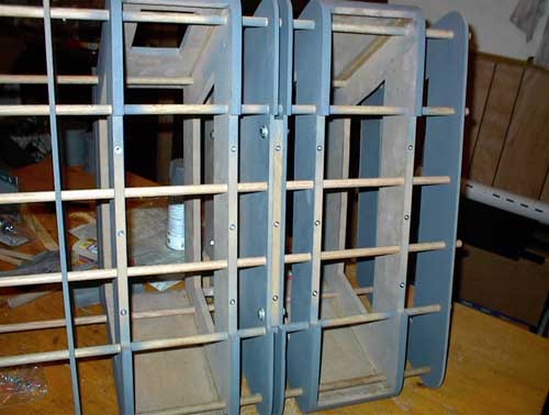
While the sides were ganged together I drilled the holes for the axles. Here is the first
stack-up of the sides which gave me a feel for how big this robot is actually going to be--huge.
Before continuing I cut out the center section of the outer three pieces on each side and a groove
into the bottom of the six center pieces to fit the underplate.
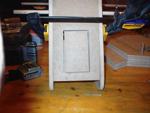
The soil sampler door was simply cut out of the right foot section using a jeweler's jigsaw
blade to leave as small a kerf as possible. The hinges are #6-32 bolts with the heads cut off after
they were screwed in. Slots were cut for these hinge pins and a cover plate was fashioned so that
the door doesn't swing inward past the rest of the foot section.
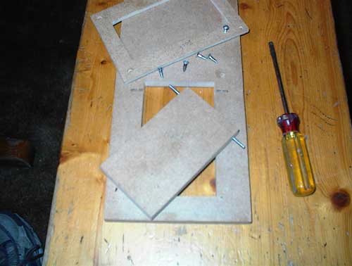
Here is the soil sampler door assembled into the foot panel which is ready to attach to the sides.
The soil sampler panel is ready to attach using screws and glue.
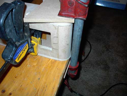
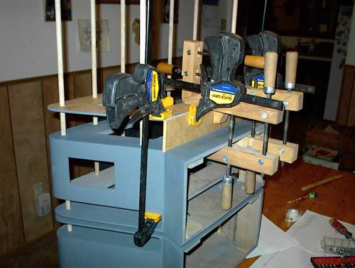
Even though the panels were predrilled for the screws, the MDF still cracked near each edge of each panel.
I was able to glue the cracks back closed using these wooden clamps.
One reason you might want to buy tools at some place other than Harbor Freight. I broke this
screw clamp while gluing one of the MDF splits.
By using the screw clamps to put pressure on the panels before putting the screws in I was able
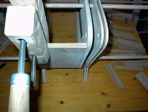
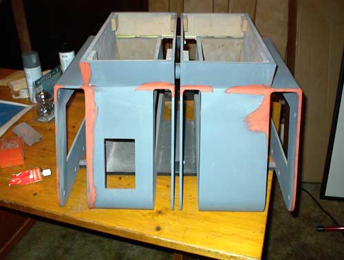
to avoid the cracking. Second big mistake is shown here in the form of the white spots on this edge. On the left
foot section I glued the end panels between the correct side panels but had them backwards. Since this side does not
have any distinguishing characteristics (like a soil sampler door) I should have been able to simply flip the
left foot around and use it. But, I had not drilled the axle holes exactly in place and turning this section around
made the holes mismatched. The white spots on the panel you see are wood putty used to fix the panel after I tore
the left foot apart and glued it back together in the proper orientation.
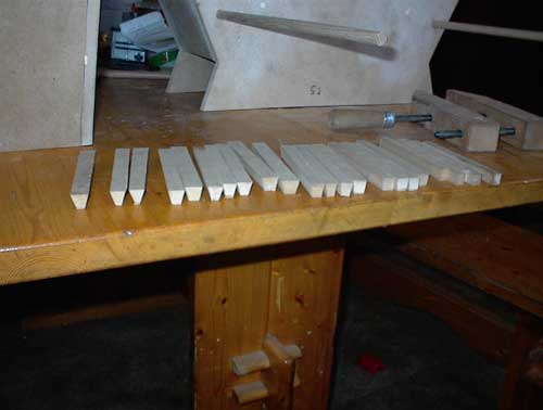
The plans call for the rounded section at the bottom of each foot to be simply the polystyrene plastic
covering. Since I won't be covering the treads with plastic I needed to fashion the rounded parts out of wood.
Here you see an assortment of "slats" I've cut at different angles that I'll use to make a blank that can be
sanded round.
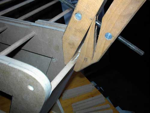
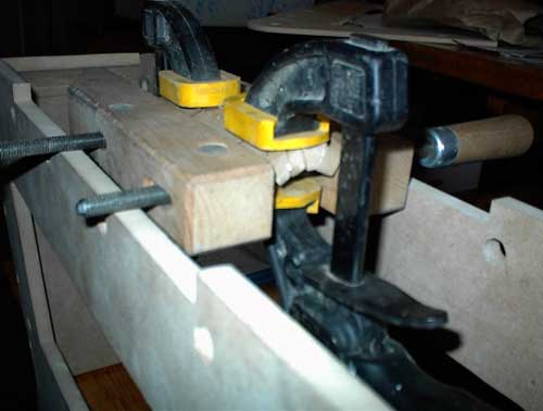
Each round was created by fitting four or five slats through trial and error. The slats were made to
stick out over the side panels and sanded to the proper curve.
I used different types of clamps to make the round sections.
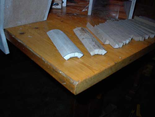
Here are two rounded sections, one freshly glued and the other with an initial sanding.
The round sections were installed using glue and brads which were countersunk and their resulting holes filled in.
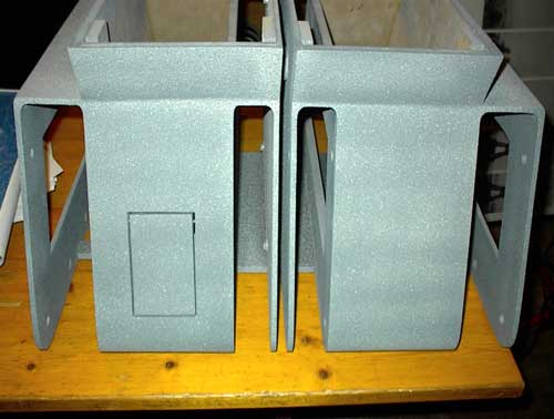
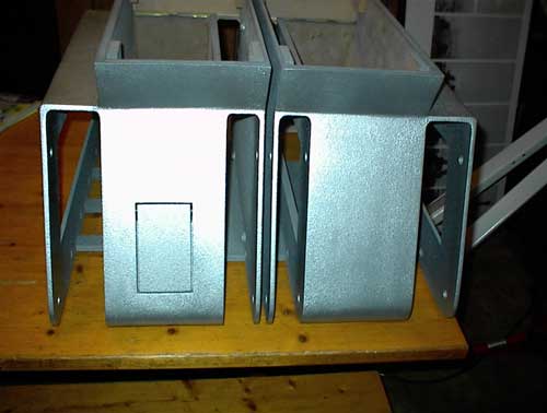
Lots and lots of sanding, filling, priming of the feet came next.
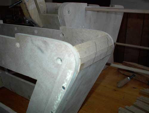
Now that the feet have been filled, sanded and primed I notched the side of the foot and the outer panel
to accept the top part that covers the wheels. The 1/8" deep dado in the foot section and the 1/16" rabbet in the
outer panel will give more gluing surfaces. These top panels were not glued at this step but much later.
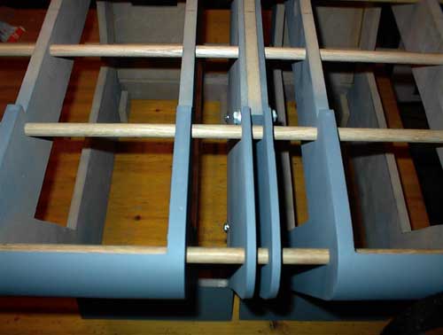
Some builders leave the feet separate, I chose to bolt mine together. I chose to put a half inch
gap between the feet, much larger than called for in the plans but correct from what I can see in the robot
publicity stills.
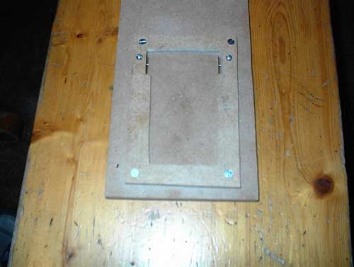
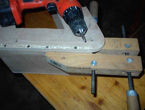
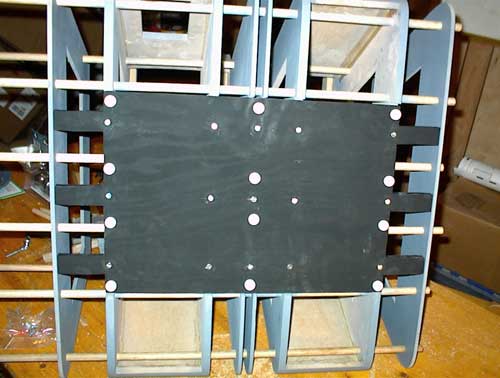
I don't know how many times I'll be installing and removing the bottom plate of my treadsections and
screw holes in MDF are notorious for loosing grip if screws are installed too often. I decided to use screw
in inserts and machine bolts so this wouldn't be a problem.
You can see my bottom plate here, with three tabs on each side instead of one (as called for in the plans). These tabs have screw in
inserts in them as well so the outer panels can be attached securely. I also used pound-in plastic feet on the
bottom plate to keep the treadsection slightly elevated until the wheels/treads are installed.
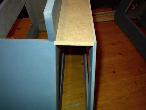
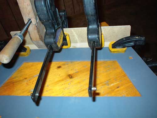
Now that the bottom plate tabs will hold the outer panel the correct distance from the foot it is time
to glue the wheel-top plate. I'm only gluing one side right now so I can reinforce the joint.
I added this angled cleat to strengthen the wheel-top plate to outer panel joint. I plan to round the
outer side of this joint and hope this cleat will keep my glued edges from cracking.
I used wood filler, body filler (Bondo), and spot putty to make the treadsection smooth and uniform.
Note that I created the fillets on the top of the wheel openings to mimic the welds in the original robot.
I spent weeks sanding, filling, sanding, priming to get the treads smooth.
I put Fleckstone texturing on the treadsection and attempted to sand it flat into a more "orange peel" look.
As I did many time before on this project, I over-sanded and had to re-coat.
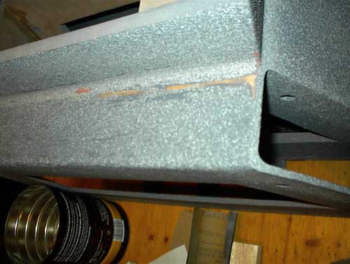
The treadsection is now textured and sanded, ready for final paint.
Here is the treadsection completed. I am mostly happy with the results. It took me just about three
months to complete this part of the project though I let the
Teardrop trailer projects
interrupt quite a bit.
| Ā | |
 |
On 4/6/04 the toybox was:
 |
 |
|
Copyright © 2005 Sam Cancilla. ĀAll Rights Reserved Worldwide.